
Structural Design and Numerical Simulation of an Implantable Axial Blood Pump
ABSTRACT
The aim of this research is to design an efficient implantable blood pump to support the blood circulation and reduce the shear stress related blood damage. Axial blood pumps have been evidenced and acknowledged in recent years because of their small size. In this study, an axial blood pump which can be easily implanted in the human body has been designed and studied. The computational fluid dynamics (CFD) analysis was performed to improve the structural design and the fluid dynamics aspects of the implantable axial blood pump. Based on established numerical methods and hydrodynamic performance testing facilities, the distributions of flow streamline, shear stress, velocity and pressure of the axial blood pump were obtained using the commercial software (ANSYS Fluent, version 12.1.2). The relationship between the rotational speed and shear stress was investigated at several rotational speeds (5,000- 9,000rpm). Also, the pump characteristic curves of the flow rate against the pressure head under different rotating speeds have been performed. The results show that the implantable axial blood pump could produce 5L/min of blood at 100mmHg through the outlet when rotating at about 6,570rpm; the rotational speed has a direct correlation with pressure drop and shear stress; the scalar shear stresses were less than 360Pa. All of these simulation findings are encouraging and demonstrate progress toward achieving an implantable axial blood pump design. In comparison with existing models for VADs, it is confirmed that the shear stresses are decreased by a little increasing in the pump diameter. These will reduce the blood exposure to shear stress significantly and consequently lower the blood damage.
KEYWORDS
Axial blood pump; Computational fluid dynamics; Numerical simulation; Shear stress
INTRODUCTION
Heart disease is currently one of the major diseases that makes human’s lives endangered. Each year about one fifth of heart disease cases will eventually develop heart failure in the world [1-4]. The heart transplant could be the only treatment option for some congenital heart disease patients. However, the short supply of donor hearts ultimately restricts the applications of heart transplant technology [4-8]. The blood pump was invented to partially or completely replace the natural heart to carry out the body blood circulation for that heart failure patients [9-13]. Centrifugal blood pumps, though much simpler and less expensive in design, are usually larger than axial blood pumps [14-16]. So, axial blood pumps can be implanted more easily, and they are more suitable for pediatric use because they are smaller and consume less power. Some studies show that a compact axial blood pump is required to run at higher operational speed than a centrifugal blood pump to build up the blood pressure head required for the desired flow rate. However, according to some literatures [7,15,17], higher speeds may lead to higher shear stresses and thus higher probability of blood damage, in addition, the degree of hemolysis can be expressed as a function of shear stress and exposure time [7,18]. Therefore, the damage of the red cells can also increase with time. Some researchers solve this problem by using bigger size in diameter and smaller size in length [15]. Certainly, the clearance between the rotor and casing has great effect on the axial blood pump performance. Axial blood pumps with various structural exhibit different hydraulic and hematologic performances. Therefore, it is essential to optimize the structural of blood pump for the purpose of improving pump performance and reducing the level of shearrelated blood damage. So as to execute the design modifications, both computational fluid dynamics analysis and hemolysis tests in vitro are feasible. Compared with CFD, the hemolysis tests in vitro require huge investment of time and money [7,19,20]. Therefore, CFD analysis has been widely used for blood pump development and analysis of its hydraulic performance and hemocompatibility [6,21].
For the purpose of designing an implantable axial blood pump with best hydraulic performance, in this paper, we mainly concentrate on the structure design, CFD modeling and flow field analysis of the axial blood pump including the inlet, straightener, impeller, diffuser and outlet. The CFD modeling provided some valuable information in determining the appropriate parameters of pump to improve pump efficiency and avoiding excessive fluid shear stress. This method can be used to predict quantitatively the hydraulic potential of axial blood pumps and can be applied to the optimal selection of pump structure in its design. These results will be used to identify the deficiencies of the current designs for axial blood pumps from a fluid dynamic point of view. The hypothesis was set that, if an accurate model of the axial blood pump could be generated using CFD, it would be possible to refine the design more easily and thereby reduce the amount of blood damage.
MATERIALS AND METHODS
It is the specific application that determines the features of axial blood pump such as implant ability, durability and blood compatibility, which have been clearly indicated in some literatures [1,7,10]. Most of the requirements are not included in the conventional design theories of impeller pump. As an implantable device, the blood pump must be designed with the dimensions compatible with the installation situation. Therefore, all knowledge and experiments of blood pump are based on such a uniquely miniature feature. A combination of theoretical analysis and numerical simulations was used in this study, in which the flow field of the axial blood pump was carefully analyzed, the shear stress and pressures acting on the blade were investigated by a CFD commercial software package ANSYS FLUENT 12.1.2 (ANSYS Inc., Canonsburg, PA, USA). These approaches aided in selecting the most suitable design for the implantable axial blood pump.
Structure of blood pump
Over the past few decades, various axial blood pumps have been developed in the world. Some designs do not include a diffuser [22,23]. However, for the axial blood pump with a diffuser, there are two main types. One is that the diffuser blades and hub are integrated such as DeBakey VAD and HeartMate II [24, 25], another is that the diffuser hub is detached from the diffuser blades with a clearance gap such as LEV-VAD and Magnevad [19, 26]. The implantable axial blood pump investigated is based on the prototype made in our laboratory, Figure 1 shows the assembly of the implantable axial blood pump. The blood pump mainly consists of pump housing, straightener with 5 blades, impeller with 4 blades and diffuser with 5 blades. There is also clearance between the blade tips and pump casing, so the shear effect will often occur in these clearances.
According to some literatures [13,19, 24, 25], most axial blood pumps basically consist of a straightener region with stationary blades to reduce the tangential flow components and thus flow pre-rotation into the pump; an impeller to impart kinetic energy to the fluid; and a stationary diffuser section with blades specifically designed to convert the kinetic energy to pressure. The impeller is fastened inside a cylinder where the permanent magnet of brushless motor is also installed. The permanent magnet used to create magnetic field in the brushless motor is made of Neodymium, Iron and Boron (Nd-Fe-B). The rotor plays a key role in the performance of the axial blood pump to enhance energy conversion and provide a higher hydraulic efficiency. However, the geometric complexity may also result in manufacturing difficulties. Therefore, this study quantifies and compares the influence of structure designs in our axial blood pump.
With respect to the design of blood pump, besides the structure parameter, operation stability and material must be jointly considered. However, other accessorial components such as bearings and seals which are beyond the scope of this research are equally important [2,7,26]. In order to achieve a compact pump design for the sake of less invasive implantation, the overall size of the device becomes the most important limitation during its design. For the same pressure and capacity requirements, the pump’s operational speed is inversely proportional to the size of the pump; thus, a smaller pump corresponds to a higher rotational speed of the impeller except that the impeller volume region remains constant.
CFD modeling and mesh
We established the three-dimensional flow domain of the blood pump by using the commercial software SolidWorks 2011 (Dassault Systèmes SolidWorks Corporation, Waltham, MA, USA). Its flow domain was divided into five sections such as inlet, straightener, impeller, diffuser and outlet, as shown in Figure 2. The domain was transferred into computational grids using a commercial grid generation tool software Workbench12.1.0 (ANSYS Inc., Canonsburg, PA, USA) which can generate both structured and unstructured grids [27]. The first has an advantage in the calculation speed, but the second is superior in the applicability to complex shape. Therefore, the unstructured grid of tetrahedral and hexahedral combined was used to mesh this model, and numerical grid generation for the flow domain of the axial blood pump is shown in Figure 3. Approximately 572,000 grids were generated for the whole flow domain. Checking the meshing quality, we found that the quality of all grids is > 0.3, which indicates that the meshing results are reasonable.
CFD analysis setup
The numerical analysis was performed to solve the Reynoldsaveraged Navier-Stokes equations for fluid flow by using the commercial CFD software ANSYS FLUENT 12.1.2 which could analyze laminar and turbulent viscous flows in complex threedimensional models. For axial blood pump, the Reynolds number (Re=ρVD/μ, where D is the diameter radius of the blood pump housing, V is the rotating speed, and μ is the kinematics viscosity of blood) is about 18,000, which is far beyond the critical laminar Re of 2000–4000 [28]. Therefore, turbulence is a dominant feature of the flow, and the variables in the governing Navier–Stokes equations are decomposed into average and the fluctuating components. In order to guarantee better accuracy in numerical predication, we used the shear stress transport (SST) k-ε turbulence model because the traditional k-ε turbulence model could not accurately reflect the shear and pressure forces acting on the vane [29]. In addition, the SST k-ε turbulence model has been widely used in many other blood pump designs [4,7,20,30], and it is adopted in the present investigation.
In addition, although blood is a non-Newtonian flow, according to some literatures study [28,31], it was assumed as an incompressible and Newtonian fluid with a density of 1.05×10³kg/ m3 and a viscosity of 3.5×10⁻³ Pa·s in this study. The mass flow at the inlet and the static pressure at the outlet were defined as the boundary conditions. The wall was defined as a non-slip wall, and the impeller region was defined as a rotating frame. The calculations were completed for steady flow conditions with constant boundary conditions in time domain. A maximal convergence criterion of 1×10⁻⁴ was used for the velocity, turbulent kinetic energy, turbulent dissipation rate and the continuity in each CFD simulation of blood pump [7,31]. Also, there was not exist negative volumes throughout the mesh.
Hemolysis prediction
Hemolysis is the damage of the red blood cells and is evaluated by the amount of hemoglobin released from the red blood cells to the plasma. The hemocompatibility estimation of blood pump is important for the development of an implantable axial blood pump. Therefore, the defects of blood pump are determined by measuring the plasma free hemoglobin and calculating the normalized index of hemolysis.
Hemolysis testing is the most common method to determine the hemocompatibility properties of blood pump. For in vitro hemolysis test, the normalized index of hemolysis (NIH) was calculated by the following equation [7,32]:
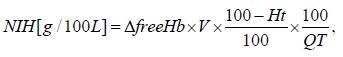
Where, ΔfreeHb is the increasing in plasma free hemoglobin concentration, V is the total volume of blood in the circuit, Q is the flow rate, Ht is the hematocrit, and T is the sampling time interval.
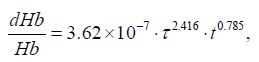
The hemolysis test has a high reliability, but this procedure is highly time-consuming and cost intensive. Today, CFD are widely used as complementary tools for blood pump development. Therefore, some researchers have developed theoretical models to estimate blood trauma by means of CFD [7,18,32,33]. The most commonly used model was obtained from the experiments results and it was expressed as a function of shear stress τ and exposure time t [7,18]:
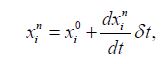
For each red blood cell, the exposure time can be achieved by using a forward Euler approach and can be described by equation:
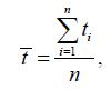
So, the mean exposure time for each red blood cell, is given by equation, as follows:
In addition, the shear stress can also be obtained by using CFD analysis. Many studies have been carried out to evaluate hemolysis of blood pumps. Sutera reported that blood damage threshold of 250Pa for the exposure time of 4min [33], Hasenkam proposed that the exposure time is 1ms with Reynolds shear stress of 250Pa [34], but Throckmorton suggested that the threshold value of 500Pa for exposure time of 100ms [35]. According to above literatures study, there are different and controversial criteria for the cell rupture, but it could be observed that the shear stress rises gradually with the decreases of the exposure time. In this paper, we will adopt this approach (Giersiepen’s equation) to evaluate the hemolysis performance of the implantable axial blood pump.
A comparison experimental system has been set up to investigate the CFD prediction results and experimental results, as shown in Figure 4. It was assembled with an axial blood pump, a reservoir, two pressure probes, one ultrasonic flow meter, one resistance and some tube connections. All the connections were PVC tubes of 10mm diameter. The fluid used in this experiment was mixed with 70% water and 30% glycerine.
The implantable axial blood pump prototype is manufactured, which is 65mm in length and 30mm in diameter, as shown in Figure 5,6. With this experimental setup, the impeller is driven at the speed range of 5,000-9,000rpm, which is adjusted by a motor controller. The blood pump operating ranges could be reproduced with flow rate 3-7 L/min at about 100mmHg blood pressure head. The pressures were measured at the pump inlet and the outlet respectively, the flow rate was measured at the outlet of the blood pump by means of a flow meter. The pressure head and the flow rate could be controlled by adjusting the resistance attached to the outflow tubing and the operational speed of the blood pump. The rotational speed was measured by counting the frequency of the pulse width modulated motor current signals.
RESULTS AND DISCUSSION
By the aid of CFD, hydraulic performances were determined for the implantable axial blood pump. The generation of pressure-flow curves, pressure distribution curves, velocity distribution curves and shear stress distribution curves have been predicted by the computational fluid dynamics analysis. The following sections detail the results of the CFD analysis for axial blood pump and capture the internal flow field information of implantable axial blood pump.
Hydrodynamic performance
The flow field of axial blood pump is very complex, and its structural parameters have influence on each other. The numerical simulations of axial blood pump with optimization structure were conducted under the flow rate of 3-7L/min and rotating speed of 5,000-9,000rpm. For each rotational speed, the pressure rise across the pump was determined. The pump characteristic curves of the flow rate against the pressure head under different rotating speeds are shown in Figure 7. Each point corresponds to the static pressure head for a giving flow rate and rotating speed.
Figure 7 shows the CFD-predicted head pressure versus pump flow in comparison with the experimental results, it can be observed that the implantable axial blood pump can generate a pressure of approximately 100mmHg at a flow rate of 5L/min. In addition, the pressure head developed causes the flow rate to increase with a corresponding increase in speed. Untaroiu et al. [13]; Chan et al. [19]; Zhu et al. [23] found similar pump characteristic curves of the axial pumps. Normally, the flow rates of a blood pump for an adult range from 4-6L/min, so all these designs can generate an adequate static pressure head higher than 100mmHg at a rotating speed of 6,570rpm. We compared the simulation results with research results of some literatures [19,28,36,37], the calculated hydrodynamic performance of the axial blood pump can meet the design conditions.
Flow streamlines
The fluid flow patterns throughout the blood pumps are extremely important. Any irregular flow pattern or reverse flow in any part of the pump can cause blood thrombosis. The blood flow streamlines throughout the blood pump has been shown in Figure 8. The flow streamlines are passing through the pump and around its interior component: straightener, impeller and diffuser. As expected, these streamlines demonstrate no sign of separation, vortices or reverse flow except for a slight flow distortion in the interface region of stationary and rotating parts. From Figure 8, it can be observed that some path lines from the impeller outlet flowed into the clearance gap between the rotor cylinder and the pump housing, and finally rejoined the main flow in the impeller. Furthermore, there was no vertex in the clearance gap.
The contour plot of velocity distribution is shown in Figure 9, which include the velocity distribution in the cross sections in the flow domains. As shown in the figure, the velocity increases from pump inlet to impeller, then decreases from impeller to pump outlet. This is because that there is decreasing velocity to provide adequate pressure for blood pump.
Figure 10 displays the velocity vectors distribution of blood pump which is obtained in CFD-post. The velocity distribution is relatively regular, but the flow field shows some disordered features in the interface between impeller and diffuses. It can be observed that the blood enters the straightener of pump at the lowest speed; the flow decelerates in the axial direction upon entering the impeller whose rotation then accelerates the flow in the circumferential direction. The varying pitch of the impeller leads to an increase in tangential speed with axial distance along the impeller. At the surface of the impeller shaft tangential speeds of 3.8m/s are observed. It rises to about 6.25m/s at the outer wall. The flow exits the rotating impeller into the stationary diffuser blades; the deceleration of the high-speed rotational flow generates a large pressure head at the end of the blood pump. This drives the flow forwards and out of the pump at an appropriate flow rate and pressure for cardiac assistance.
Flow shear stress
The shear stress is the main source of hemolytic effects, which can damage red blood cells. Paul’s research shows that a significant increase in blood image can be observed for shear stress>425Pa and for exposure time>620ms in laminar Couette flow [38]. Figure 11 depicts the shear stress distribution throughout the blood pump. From Figure 11, at the design point, as can be seen most of the body area under shear stress about 100Pa, the maximum shear stress s of 360Pa were estimated to exist along a small surface area at the leading edge of the impeller blades along the blade tips. That’s mostly because the clearance between the impeller and casing should be appropriate to reduce the reflux. If the clearance is too big, some amount of the leakage flow tends to adhere to the housing without contribution to the pump pressure rise. The leakage flow can also generate a jet leakage vortex that interacts and mixes with the primary flow, causing hydraulic loss and possibly inducing blood trauma.
Figure 12 shows that the maximum shear stress valve is relatively small, but the maximum value concentrates in the inlet of impeller due to the variation of the vane entering angle. Namely, the bigger twisting vane causes more variation of the blood flow velocity, which leads to large shear stress. From Figure 12, we know that the value of maximum shear stress valve is about 360Pa, but it does not exceed 400Pa, which is the tolerating upper limit of blood damage under long exposure time.
Hemolysis analysis
We have estimated hemolysis of the implantable axial blood pump by applying the parameter obtained from CFD analysis based on the particle tracking method to the above model. We selected 103 uniform path lines of particles as the trace of red blood cells at the inlet of blood pump. Figure 13 is the accumulated damage index of one streamline. The estimated hemolysis index E is defined as the average damage of all the trace lines, which is shown in Figure 14. According to the research results of some literatures [7,29,39], the estimated hemolysis index E range from 0.005 to 0.042. The E value of the implantable axial blood pump is about 0.014 at rotating speed of 7,000rpm, which indicates that this blood pump has good hemolytic property and can meet the basic requirements of hemolytic blood pump performance. As exhibited in Figure 14, when the number of the rotating speed increases from 5,000rpm to 9,000rpm, the estimated hemolysis index E of the blood pump increase correspondingly.
Comparison
Table 1 compares the design point and dimensions of the present VAD and four other VADs [15,40,41]. These axial blood pumps produce the same range of flow rates and pressure heads; however, their rotational speeds are different. The present pump was designed to work at 6,570rpm which is lower than that of others but is higher than Koochaki’s VAD and LEV-VAD2. So, the risk of hemolysis occurrence is much lower, therefore the pump is more reliable. The overall length and diameter of the pump are 65 and 30 mm respectively. Comparing these axial blood pumps, the length of pump decreased; however, the diameter of Koochaki’s VAD increased 14.28%, so that the lower speed [15]. These values indicate that how this design optimizes overall blood pump dimensions for implanting.
DISCUSSION AND CONCLUSION
Computational fluid dynamics is a very important tool that can be used effectively to evaluate and improve pump design [28,31,37,39,42]. This study employed CFD analysis to design an implantable axial blood pump. A three-dimensional model of blood pump has been designed and established by SolidWorks 2011, the local flow field, pressure, shear stress, hemolysis prediction and pump performance has been analyzed. In order to satisfy biological objectives for these dimensions, the structure of optimization was designed. The fluid dynamics aspects of the pump were calculated; also, the hemolysis and comparison with some VADs were performed. Meanwhile, using only a CFD study is premature to formulate a conclusion, in our subsequent study, vitro experiments have to be carried out to validate our conclusion. Furthermore, in addition to blood damage [43], animal experiments, and so on [44,45] should also be carried out in future research.
ACKNOWLEDGEMENT
The project was supported by National Natural Science Foundation of China with grant numbers 51275371 and the Fundamental Research Funds for the Central Universities (WUT: 143204004).
REFERENCES
- Kwon MH, Moriguchi JD, Ardehali A, Jocson R, Marelli D, et al. (2009) Use of ventricular assist device as a bridge to cardiac transplantation: Impact of age and other determinants on outcomes. Tex Heart Inst J 36(3): 214- 219.
- Wu HC, Gong G, Wang ZQ, Hu Y, Song C (2014) Structural design and numerical simulation of the diffuser for maglev axial blood pump. J Mech Med Bio 14(3): 1-19.
- Wappenschmidt J, Sonntag SJ, Buesen M, Gross-Hardt S, Kaufmann T, et al. (2017) Fluid Dynamics in Rotary Piston Blood Pumps. Ann Biomed Eng 45(3): 554-566.
- Li TY, YE L, Hong FW, Liu DC, Fan HM, et al. (2013) The simulation of multiphase flow field in implantable blood pump and analysis of hemolytic capability, Journal of Hydrodynamics 25(4): 606-615.
- Wiegmann L, Boe S, Zelicourt D, Thamsen B, Schmid M, et al. (2018) Blood pump design variations and their influence on hydraulic performance and indicators of hemocompatibility. Ann Biomed Eng 46(3): 417-428.
- Kido K, Hoshi H, Watanabe N, Kataoka H, Ohuchi K, et al. (2006) Computational fluid dynamics analysis of the pediatric tiny centrifugal blood pump (Tiny Pump). Artif Organs 30(5): 392-399.
- Behbahani M, Behr M, Hormes M, Steinseifer U, Arora D, et al. (2009) A review of computational fluid dynamics analysis of blood pumps. European Journal of Applied Mathematics 20(4): 363-397.
- Gupta P, Blanco C, Madigan M, Dodgen A, Hanson M, et al. (2012) Solid organ donation in a child after extracorporeal membrane oxygenation, orthotropic heart transplantation, and ventricular assist device support. Pediatr Transplant 16(8): 368-371.
- Butler KC, Maher TR, Borovetz HS (1992) Development of an axial flow blood pump, ASAIO Journal 38: 296-300.
- John R (2008) Current axial-flow devices-the Heart Mate II and Jarvik 2000 left ventricular assist devices, Semin Thorac Cardiovasc Surg 20(3): 264-272.
- Wu HC, Wang ZY, Lv XJ (2011) Design and simulation of axial flow maglev blood pump. Int J Info Engg & Electro Bus 3(2): 42-48.
- Leme J, Fonseca J, Bock E, da Silva C, da Silva BU, et al. (2011) A new model of centrifugal blood pump for cardiopulmonary bypass: design improvement, performance, and hemolysis tests. Artif Organs 35(5): 443-447.
- Chan WK, Wong YW, Ong W, Koh SY, Chong V (2005) Numerical investigation of the effects of the clearance gap between the inducer and impeller of an axial blood pump. Artif Organs 29(3): 250-258.
- Helmut MR, Mustafa A (2000) Blood pumps for circulatory support. Perfusion 15(4): 295-311.
- Mojtaba K, Hanieh NO (2013) A new design and computational fluid dynamics study of an implantable axial blood pump. Australasian Physical & Engineering Sciences in Medicine 36(4):417-422.
- Jahanmir J, Hunsberger AZ, Ren ZH, Heshmat H, Heshmat C, et al. (2009) Design of a small centrifugal blood pump with magnetic bearings. Artificial Organs 33(9): 714-726.
- Kang C, Huang QF, Li YX (2014) Fluid dynamics aspects of miniaturized axial-flow blood pump. Biomed Mater Eng 24(1): 723-729.
- Giersiepen M, Wurzinger LJ, Opitz R, Reul H (1990) Estimation of shear stress-related blood damage in heart valve prostheses in vitro comparison of 25 aortic valves. Int J Artif Organs 13(5): 300-306.
- Untaroiu A, Wood HG, Allaire PE, Throckmorton AL, Day S, et al. (2005) Computational design and experimental testing of a novel axial flow LVAD. ASAIO J 51(6): 702-710.
- Fraser KH, Taskin ME, Griffith BP, Wu ZJ (2011) The use of computational fluid dynamics in the development of ventricular assist devices. Med Eng Phys 33(3): 263-280.
- Anderson J, Wood HG, Allaire PE, Olsen DB (2000) Numerical analysis of blood flow in the clearance regions of a continuous flow artificial heart pump, Artif Organs 24(6): 492-500.
- Mitamura Y, Nakamura H, Okamoto E, Yozu R, Kawada S, et al. (1999) Development of the valvo pump: An axial flow pump implanted at the heart valve position. Artif Organs 23(6): 566-571.
- Zhu X, Zhang M, Zhang G, Liu H (2006) Numerical investigation on hydrodynamics and biocompatibility of a magnetically suspended axial blood pump. ASAIO J 52(6): 624-629.
- Wieselthaler GM, Schima H, Hiesmayr M, Pacher R, Laufer G, et al. (2000) First clinical experience with the DeBakey VAD continuous-axial-flow pump for bridge to transplantation. Circulation 101: 356-359.
- Goldowsky M (2004) Magnevad-the world’s smallest magnetic-bearing turbo pump. Artifi Organs 28(10): 945-952.
- Liu GM, Zhang Y, Chen HB, Sun H, Zhou J, et al. (2014) Flow visualization in the outflow cannula of an axial blood pump. Biomed Mater Eng 24(1): 117-122.
- ANSYS, Inc. ANSYS Workbench User’s Guide, ANSYS, Inc. Canonsburg, PA, USA.
- Chua LP, Su B, Lim TM, and Zhou T (2007) Numerical simulation of an axial blood pump. Artif Organs 31(7): 560-570.
- Chen ZS, Yao ZH, Zhu LL, Zhang XW (2013) Hemolysis analysis of axial blood pumps with various structure impellers. Journal of Mechanics in Medicine and Biology 13(4): 1-15.
- ANSYS, Inc. Ansys CFX program documentation, ANSYS, Inc. Canonsburg, PA, USA.
- Throckmorton AL, Untaroiu A (2008) CFD analysis of a Mag-Lev ventricular assist device for infants and children: fourth generation design, ASAIO J 54(4): 423-431.
- Yano T, Sekine K, Mitoh A, Mitamura Y, Okamoto E, et al. (2003) An estimation method of hemolysis within an axial flow blood pump by computational fluid dynamics analysis. Artif Organs 27(10): 920-925.
- Sutera SP, Mehrjardi MH (1975) Deformation and fragmentation of human blood cells in turbulent shear flow. Biophy J 15(1): 1-10.
- Hasenkam JM, Nygaard H, Giersiepen M, Reul H, Stødkilde H et al. (1988) Turbulent stress measurements downstream of six mechanical aortic valves in pulsatile flow model. J Biomech 21(8): 631-645.
- Throckmorton AL, Untaroiu A, Allaire PE, Wood HG, Matherne GP, et al. (2004) Computational analysis of an axial flow pediatric ventricular assist device. Artif Organs 28(10): 881-891.
- Untaroiu A, Throckmorton AL, Patel SM, Wood HG, Allaire PE, et al. (2005) Numerical and experimental analysis of an axial flow left ventricular assist device: the influence of the diffuser on overall pump performance. Artif Organs 29(7): 581-591.
- Apel J, Neudel F, Reul H (2001) Computational fluid dynamics and experimental validation of a micro axial blood pump. ASAIO J 47(5): 552-558.
- Paul R, Apel J, Klaus S, Schügner F, Schwindke P, et al. (2003) Shear stress related blood damage in laminar couette flow. Artif Organs 27(6): 517-529.
- Kosaka R, Nishida M, Maruyama O, Yamane T (2011) Development of a miniaturized mass-flow meter for an axial flow blood pump based on computational analysis. J Artif Organs 14(3): 178-184.
- Fan HM, Hong FW, Zhang GP, Ye L, Liu ZM (2010) Applications of CFD technique in the design and flow analysis of implantable axial flow blood pump. Journal Hydrodynamics Ser B 22(4): 518-525.
- Untaroiu A (2006) LEV-VAD2 axial flow blood pump:optimized flow path design by means of computational fluid dynamics. University of Virginia, Charlottesville, USA.
- Demir O, Biyikli E, Lazoqlu I, Kucukaksu S (2011) Design of a centrifugal blood pump: heart turcica centrifugal. Artifi Organs 35(7): 720-725.
- Hentschel B, Tedjo I, Probst M, Wolter M, Behr M, et al. (2008) Interactive blood damage analysis for ventricular assist devices, IEEE Trans Vis Comput Graph 14(6): 1515-1522.
- Su B, Chua LP, Wang XK (2012) Validation of an axial flow blood pump: computational fluid dynamics results using particle image velocimetry. Artif Organs 36(4): 359-367.
- Cho YH, Deo SV, Schirger JA, Pereira NL, Stulak JM, et al. (2012) Implantation of a heartmate II left ventricular assist device via left thoracotomy. Ann Thorac Surg 94(5): 1712-1714.
Article Type
Research Article
Publication history
Received date: November 12, 2019
Published date: November 27, 2019
Address for correspondence
Huachun Wu, School of Mechanical and Electronic
Engineering, Wuhan University of Technology, China
Hubei Provincial Engineering Technology Research Center for Magnetic Suspension,
Wuhan University of Technology, China
Copyright
©2019 Open Access Journal of Biomedical Science, All rights reserved. No part of this content may be reproduced or transmitted in any form or by any means as per the standard guidelines of fair use. Open Access Journal of Biomedical Science is licensed under a Creative Commons Attribution 4.0 International License
How to cite this article
Weibo Y, Huachun W, Yefa H. Structural Design and Numerical Simulation of an Implantable Axial Blood Pump. 2019 - 1(3) OAJBS.ID.000121.
Figure 1: Assembly of an implantable axial blood pump.
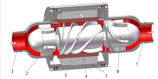
1-Inlet, 2-Straightener, 3-Impeller, 4-Motor, 5-Housing, 6-Diffuser, 7-Outlet.
Figure 2: Flow domains of axial blood pump.
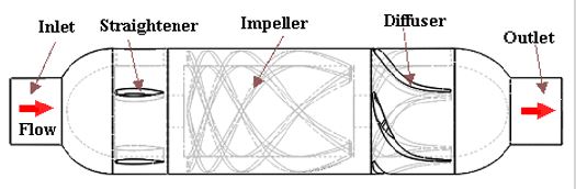
Figure 3: Computational grids of axial blood pump.
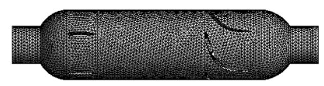
Figure 4: The simulation circuit and test rig for pressure performance curve.
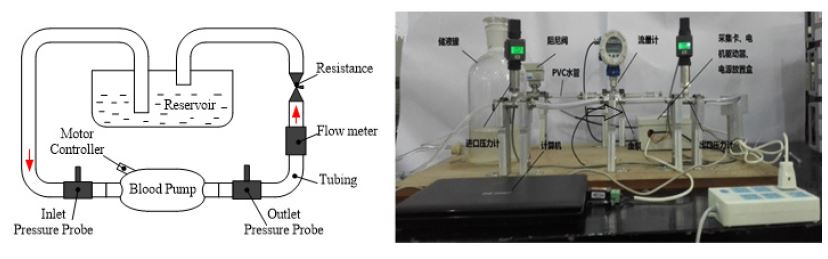
Figure 5: Implantable axial blood pump.
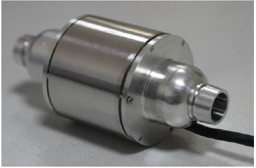
Figure 6: Impeller and casing components.
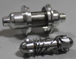
Figure 7: Hydrodynamic performance curve of blood pump.
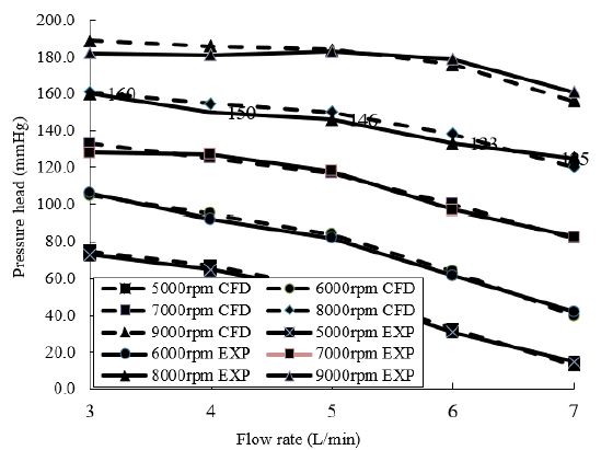
Figure 8: Fluid streamlines in the pump at 7,000rpm rotational speed and 5L/min flow rate.
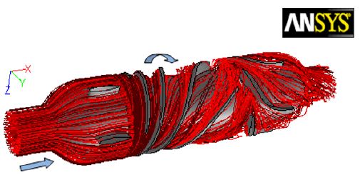
Figure 9: Velocity distribution at 7,000rpm rotational speed and5 L/min flow rate.

Figure 10: Velocity distribution at 7,000rpm rotational speed and 5L/min flow rate.
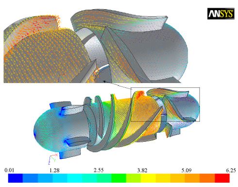
Figure 11: Static pressure distribution at 7,000rpm rotational speed and 5L/min flow rate.
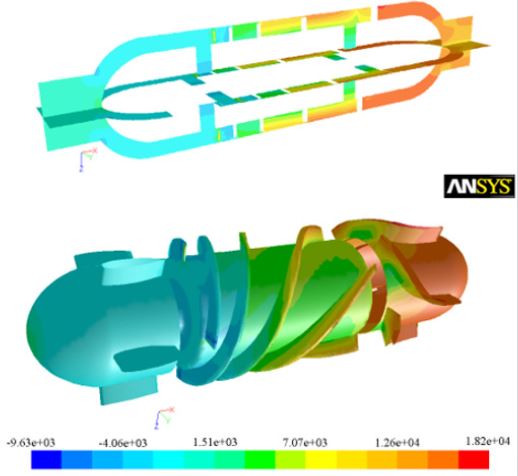
Figure 12: Wall shear stress distribution at 7,000rpm rotational speed and 5L/min flow rate.
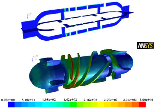
Figure 13: The accumulated damage index at 7,000rpm rotational speed and 5L/min flow rate.
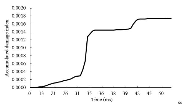
Figure 14: The estimated hemolysis index with different rotating speeds.
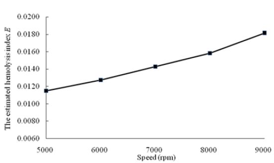
Table 1: Various axial blood pumps.

