Numerical Study of the Pedicle Screws’ Pullout: Design of Experiment and Results Processing Using the ‘Taguchi’ Method
ABSTRACT
The objective of this research is to use the Taguchi method to study the effects of parameters that affect the pull out of pedicle screws. These parameters are biological-based (normal or osteoporotic bone types, pedicle diameter), design-based (screw’s outer diameter, thread depth, pitch, and shape) and surgical-based (preparation hole, bone-screw contact type). A total of seven (7) parameters having each two (2) levels each. Using 2D axisymmetric finite element computational models, a series of “Taguchi” simulation tests based on an orthogonal L8 [27] lattice is conducted.
The method aims to reduce the (27) or (128) possible combinations of simulations to eight (8) and thereby, classify the chosen parameters according to their degree of influence on the results. As expected, the study confirmed the significance of bone density in spine fixation procedures. The computed pullout strength for the osteoporotic bone drastically dropped compared to normal bone. The low-density bone characterizing elderly is found to lose ~65% of its pull-out strength with age. The design parameters are classified according to the deviation they inflict to the model responses, at small early and final stages of the loading, for normal and osteoporotic bone conditions, respectively. The bonded contact type, assured by the use of acrylic cement layer and a cylindricalshaped pedicle screw are found to procure the highest impact on the response of the screw-vertebra complex, irrespective to the bone condition.
In opposition, the pedicle screw thread depth and the preparation hole procuring a clearance around the screw are found to least affect the strength and stiffness of the vertebra. In general, the use of a thin acrylic cement layer along with hydroxyl-apatite coated pedicle screws, implemented in the simulation as a bonded contact between bone and screw, is found to improve the pull-out strength since it does strengthen the threads anchoring sites at the vicinity of the bone either normal or osteoporotic. Conversely, non-cemented smooth tapered screws can speed up the failure mechanism for normal and osteoporotic bone-screw complex under large deformations. When performing the surgery on an elderly patient with a known osteoporotic vertebral bone and small pedicle size, the current study suggests the use of acrylic cement and a cylindrical pedicle screw having the largest allowable diameter and the smallest thread depth and pitch. The vertebral failure modes are classified according to the degree of severity, associated with the amount of strain energy stored and released at failure. The most drastic mode led to the intense disruption of the pedicle and large amounts of trabecular and subcortical bone. A less severe mode was characterized by the pedicle cortex breakage along with strips of subcortical and trabecular bone confined between the screw threads. Finally, the least drastic mode was typically represented by the screw gliding outside the vertebra without impairing the pedicle.
KEYWORDS
Finite element; Pullout strength; Taguchi method; Vertebral fracture; Pedicle screws; Spinal fixation; Osteoporosis
INTRODUCTION
The pedicle screwing has made remarkable progress in spinal surgery. After having been considered an exceptional act for a long time, it suddenly experienced a craze, as evidenced by the current proliferation of pedicle-based osteosynthesis systems [1]. But this powerful surgical technique can only achieve its objectives in complete safety at the cost of rigorous theoretical and practical knowledge. The critical location of these screws close to the main nerve roots makes these elements very delicate in spine surgery causing serious and traumatic postoperative complications to the patient when inserted inaccurately [2]. Although the bony penetration landmarks are reliable, mastering this technique requires a proper use of multi-stage instrumentation as well as an in-depth knowledge of vertebral morphology [3].
According to Moe et al. [4], the estimated rate of pedicle screw pullout in the spine is in the order of 10 to 15%. The number of studies conducted in this area is very small. In a retrospective study, conducted by the same author, on 66 patients instrumented with “Zielke” type of spinal equipment, 12 cases of tearing were noted. Only one in 12 cases suffers from loss of correction. Esses et al. [5], on a series of 617 cases, recorded tear out rates varying from 0.6 to 11% depending on the age of the patients treated. In the same study, it was reported that 2.9 % of the pedicle screws used were severely fractured before the end of treatment.
These results show the importance that the pedicle screw can play in spinal surgery and justify the interest of this field of research in terms of simulation and numerical modeling or by experimental measurements [6]. Indeed, several cases observed post-operatively, show through standard X-rays, that the implanted screws can have trajectories and insertion depths as diverse as they are varied. Some of these screws, under the effect of excessive mechanical stress, may fracture prematurely in-vivo [7]. The trabecular architecture of cancellous bone varies and tends to be denser near the cortical bone. The orientation of the screws in the vertebra, generally converging, improves the mechanical strength of the screws, but this depends a lot on the quality of the bone and the in-vivo stress forces imposed on the assembly which can be, in several cases, very different.
Pulling out screws or loosening implants are common complications in orthopedic surgery. These pullout efforts vary in terms of amplitude and rate of loading depending upon the patient’s mobility [8]. They might be either slow, low in magnitude leading to static loading conditions or fast, with high magnitude as in the case of dynamic or impact loading conditions. The consequence of these loading conditions on the bone at the vicinity of pedicle screw anchorage is devastating, especially in the early months of stabilization. The need to study the bonding mechanisms between the pedicle screws and vertebra requires a close collaboration between orthopedic surgeons and engineers [3].
The clinical experience gained in orthopedic surgery shows that practitioners are facing occasionally problems related to the choice of the osteosynthesis material to use, depending on the lesions to be treated (traumatic cases, scoliosis deformities, etc.). The use of a surgical protocol specifies in advance, the nature of the instrumentation to be used, among other things the choice of pedicle screws, and the type of assembly to be implanted, short, long, or mixed; for the treatment, for example, of traumatic cases (fractures of vertebrae) [9]. The treatment of certain spinal injuries consists of stabilizing the spine by installing adequate osteosynthesis equipment. For traumatic cases, for example, this material behaves like a physiological load shunt system to relieve the fractured vertebra [10].
The extreme morphological variability of the vertebrae, depending on the stage, age and gender, makes universal spinal instrumentation very difficult. Improper screw placement can lead to serious and traumatic postoperative complications for the patient. Indeed, preoperatively, the installation of a pedicle screw is difficult to handle and requires special care on the part of the surgeon. It is a complex act, which does not rely on standardized methods [11].
From a clinical standpoint, the surgeon must first visually identify, the access zone of the screw on the posterior part of the vertebra, the orientation of the drilling trajectory on both sagittal and transversal planes, the choice of pedicle screw and its insertion level. From this description we conclude that the parameters to be addressed fall under three categories; design-based parameters specific to the screw (outer diameter, depth of the thread, pitch, shape, and length), anatomical parameters (pedicle diameter, vertebral bone type) and procedural parameters (insertion type, preparation hole, use of cement layer, etc.).
In the previous computational models, we discussed the influence of pedicle screw insertion type and depth on the pullout strength of both normal and osteoporotic bones [12]. By replicating the conditions that have led to the best pullout strength, the current study aims to further analyze the influence of an additional set of parameters, judged by several authors to have the highest impact spinal fixation biomechanics [13]. Such parameters are related to screw design, morphology of the vertebra and surgical procedure. Seven parameters are adopted in the current study, and each has two possible values or levels. The interplay between these parameters requires the use of the “TAGUCHI” method that has the advantage of planning and reducing the number of tests [14] to a minimum possible number of experiments, performed within the permissible limit of factors and levels.
All our computational investigations are conducted for two configurations of the bone density: a mineralized normal bone, characteristic of a young subject and an osteoporotic bone as in elderly people. Low and high intensity prescribed displacements are administrated to the pedicle screw to mimic the effects of the subject’s weight on the overall mechanical stability of the bonescrew structure.
This study benefited from clinical data available at the biomechanics laboratory of the M. T. Kassab, National Orthopedic Institute, Tunisia. Several clinical files on osteosynthesis of the spine [15] and different types of spinal implants (screws, plates, rod, etc.) were kindly made available to us as well as the CAD and CAE software such as Solid works, CATIA, ANSA and ABAQUS used for the purpose of this research.
MATERIALS AND METHODS
In order to generate the 2D Computer Assisted Design (CAD) model, a portion of the vertebra and the screw were isolated at the screw centerline level to keep the axis of symmetry of the screw, through which the pull-out efforts are transmitted. This permits to abridge a complex 3D structure into a simpler 2D axisymmetric model that is accurately representative of an adult lumbar vertebra.
Geometric Considerations
To reflect the multi-scale aspect of the bone, the transverse process is virtually incised and a segment of the vertebral body surrounding the pedicle screw is isolated (Figure 1a). This segment, idealized in Figure 1b, represents the domain of bone tissue affected by the implant’s tearing and loosening. Such idealization is helpful in the delineation of the cortical, subcortical, and trabecular bone tissues prior to the implementation of their mechanical properties [16].
It is worth mentioning that the pedicle is constituted of cortical and subcortical bone tissues and the cortical bone shell all around the vertebral body is assumed to have a uniform thickness of one (1) millimeter [17,18]. Figure 1c emphases the dimensions pertaining to the development of the models, particularly those describing the screw threads [19]. Those dimensions are set according to the British standards [20]. Table 1 lists the labels, descriptions and values for the bone dimensions and pedicle screw nomenclature used as a basis for the reconstruction of the CAD models. It is to be noted that the values for the bold underlined labels in Table 1 are set as parameters throughout this study and are amply described in sections below.
Stress-Strain Relationship for Vertebral Bone Structures
The mechanical behavior of the human vertebral cortical, subcortical, and trabecular bone structures is described in several studies [21].
To simulate high loading conditions leading bone failure, we opted for an elastic-perfectly plastic behavior that describe the stress-strain relationships in the elastic zone and perfect plastic zone to end up to abrupt failure [22].
All the parameters associated with the stress-strain relationship for the cortical, subcortical, and trabecular bone structures, in their normal and osteoporotic conditions are grouped in Table 2.
The young’s modulus (E), the plastic yield stress ( p) and strain ( p) were deduced from density values based on empirical relations.
Also listed in this table are, the mechanical properties of the titanium alloy used for the pedicle screws.
Mesh Generation and Boundary Conditions
The discretization process of the model passed through critical steps prior to mesh generation. A preliminary investigation was performed to find the optimal mesh parameters for each model constituent. That is, in this phase, a minimal number of elements and nodes was sought to achieve appropriate convergence of the computed results. The grid density was then increased to account for higher stress gradient occurring at the screw-bone interface, an intricate area responsible for the load transfer (Figure 2).
The linear axisymmetric 4-nodes quadrilateral elements were preferred to their linear triangular counterparts due to their ability in producing regular meshes on both sides of the interacting surfaces. Such a regular and identical mesh at the screw-bone interface for the various models permits a better comparison platform of the computed results. A mesh refinement characterized by a minimal element size of 0.1 mm was implemented in such areas, leading to a total number of nodes and elements for all models around 28000 and 27000, respectively.
By their morphological aspect, highly porous vertebrae raise a problem when it comes to compute their contact stresses and load transfer mechanisms while being in contact with an extremely stiffer material, namely, the titanium. Special attention was focused on modeling the contact at the screw-bone interface. To simulate a tensile loading condition, a prescribed displacement was imposed on the screw head via a Multi-Point Constraint (MPC) coupling condition.
The coupling condition consists of selecting the nodes on the flat area of the screw head to be coupled to a reference point (RP) located on the screw’s centerline to which a movement is prescribed to reproduce the tensile test. To get closer to the ultimate conditions that supposedly lead to implant failure, large deformation formulation was made active in ABAQUS explicit solver and trial loadings were carried out to establish the amount of load that induces large deformations on the bone structure. A 500μm shift applied to the RP at a rate of 2mm/min was found to trigger such behavior and was adopted for the future large deformation analyses. On the opposite, using the default ABAQUS standard solver, a 10 μm shift on the RP was selected for small deformation situations to simulate static, low magnitude loading conditions. An MPC equation was set to account for the material continuity of the vertebral transverse process and ensure the transmission of the cohesive forces. Finally, a fixed boundary condition was set on the outermost boundary while symmetry boundary was administrated to nodes on the model’s axis of symmetry.
Selection of Tests
In a previous study [12], the influence of the screw insertion type and depth levels on the bone’s resistance to tearing was investigated. The best pullout resistance was computed following the implementation of the ‘N1’ screw insertion technique, in which the first thread of the lengthy screw is placed immediately after the preserved pedicle cortex.
The current study replicates the same screw insertion technique and depth and further investigates seven (7) parameters believed to affect the pull-out strength of the pedicle screws. Among these parameters, four are related to the screw design; the shape, being either cylindrical or conical, the outer diameter, the pitch size, and the thread depth. Two more parameters characterize the surgical procedure: firstly, the screw preparation hole that is made either coincident with the screw inner diameter or made larger with a specific clearance and, secondly, a thin acrylic cement layer whether applied or not around the screw, this later parameter directly dictates the ‘contact type’ to be used in the simulation.
One last parameter, related to the vertebral morphology is selected and concerns the diameter of the pedicle. Each of these parameters has been assigned two possible levels or values that are amply discussed in the literature [24], some of these parameters’ data can be readily found in surgical instruments catalogs. Table 3 gathers the seven parameters denoted ‘A’ to ‘G’, their respective definitions, and levels.
For each test, the selected combination of parameter levels is representative of what is performed. In fact, surgeons commonly use screws of cylindrical or conical shape, of different pitch and thread depth, the contact between the screw and bone can be assumed as frictional or bonded. For the ‘preparation hole’ parameter denoted ‘F’, the levels chosen are either ‘No clearance’, describing a wellestablished osseointegration, or ‘0.2mm clearance’ as in the case of immediate loading without the presence of an acrylic cement layer.
The Taguchi table is based on the number of parameters and their corresponding levels. In our case, the table denoted L8 (27) is based on seven (7) parameters, having, each, two (2) values or levels ‘L1’and ‘L2’ and leading to eight (8) tests. The Taguchi method, hence, reduces the number of simulation tests from (27) or (128) to eight (8).
The left demarcated side of Table 4 represents the L8 Taguchi table that expresses, for each test, the set parameter levels used, and the performance level or output ‘Y’ achieved. Also shown on the right side of the table, the schematic representation of the CAD model characterizing the test.
Let ‘A’ be the first parameter investigated in the Taguchi table, characterized by two levels ‘L1’ and ‘L2’. The overall contribution of this parameter at its level ‘L1’, designated by ‘A1’ is calculated as the average of all test outputs where the level ‘L1’ of parameter ‘A’ appears in Table 4. The tests are namely, Test 1, 2, 3 and 4 and their corresponding outputs are Y1, Y2, Y3 and Y4, respectively, one shall write then:
A1=(Y1+Y2+Y3+Y4)/4
and similarly,
A2=(Y5+Y6+Y7+Y8)/4
To depict, for instance, the effect of parameter ‘F’ through its level ‘L2’, that arises in Test 2, 3, 6 and 7 (Table 4), the following equation is then written:
F2=(Y2+Y3+Y6+Y7)/4
RESULTS-AND-DISCUSSIONS
All the Taguchi tests are conducted using one of the most broadly screw insertion technique used by surgeons, referred to as ‘N1’ in our previous study [12]. In this technique the surgeon preserves the pedicle cortex and completely inserts the pedicle screw until the first tooth crosses the cortical shell and keep pressing its inner wall.
The small deformation hypothesis (SDH) is adopted, for all tests, using a 10μm prescribed displacement to evaluate the pullout force, the pullout energy, and the stiffness of the bone-screw connection. Similarly, to evaluate the ultimate pullout force, the calculations are performed using the explicit, large strain dynamics solver, under a 500μm prescribed displacement.
Result of Taguchi Tests for Normal Bone
Table 5 displays the pullout force, the pullout energy, the stiffness of the connection and the ultimate pullout force for all tests assuming a normal bone condition. The data collected fluctuated between the various tests with Test 4 providing the smallest values and Test 3 the largest. The test output variations are found to be around ~37% for the output data collected using the small deformations approach and about 46% for ultimate pullout computed at large deformations.
The results suggest that when inserting a screw in a normal bone through a small pedicle size, the surgeon must imperatively use acrylic cement on a cylindrical shaped screw that has the largest allowable diameter as well as the smallest thread depth and pitch (Test 2, 4, 5, and 7); Table 5.
Further statistical calculations are conducted to explore the influence of each parameter level on the pullout force, pullout energy, stiffness of the connection at 10μm and the ultimate pullout force at 500μm, respectively, assuming a normal bone condition. Each one of these findings represents the average of selected separate test output results given in Table 5, according to the equations discussed in the methodology section. These findings are organized below in Table 6 with a prompt indication of the variation trend, either increasing (↑) or decreasing (↓). It is worth mentioning that varying a specific parameter from L1 to L2, leads, generally to similar variation trends for all model responses.
Parameter ‘G’ addressing the contact type effects, influenced most the model responses for the normal bone. A frictional and bonded contact conditions led to the smallest and largest model responses, respectively.
That is, a bonded contact induced around 13% increase in the pullout, energy, and stiffness at 10μm compared to their counterpart values while assuming a frictional contact. This variation reached 20.5% when computing the model response under large deformations.
The least impact is seen when varying the thread depth ‘B’ from L1=0.7mm to L2=1mm, inducing a decrease of less than 1% for the model responses computed under small deformations but caused, in turn, an increase of 1.6% in the ultimate pullout force.
A detailed classification of the design parameters according to their degree of influence on the overall model responses at small and large deformations for normal and osteoporotic bone conditions is addressed in section 5.3 below.
Result of Taguchi Tests for Osteoporotic Bone
Table 7 gathers findings for the pullout force, the pullout energy, the stiffness of the connection and the ultimate pullout force for all tests assuming, this time, an osteoporotic bone condition. The data collected fluctuated between the various tests with Test 4 providing the smallest values and Test 5 the largest. The test output variations are found to be around ~50% for the data collected at 10μm and 53% for the ultimate pullout at 500μm. Under 10mm displacement, the pullout forces are very low, not exceeding 70N, irrespective of the variation of the intrinsic or extrinsic parameters.
Under large deformations, the ultimate pullout load, reaching at most 1164N (Test 5) is accompanied by an extensive rupture of the bone matrix (cortical, subcortical, trabecular). Such large deformation loading is epitomized, clinically, by high amplitude mobility arising on the spine during impacts such as sudden falls and automobile accidents. In addition, when compared to normal bone, osteoporotic bone has undergone a deterioration in the ultimate pullout strength, oscillating between a minimum of 58% and a maximum of 64%, calculated from test 7 and test 1, respectively. This drop is absolutely justifiable when the architectural aspect of the bone is taken into consideration. Indeed, when the porosity invades the bone tissue, the effective contact surfaces between the bone and the implant drastically decreases, promoting the advent of pullout phenomena at relatively low loads.
Similar to the previous findings in normal bone, inserting a screw in an osteoporotic bone condition through a small pedicle size, necessitates the use of acrylic cement layer over cylindrical screw that has the largest allowable diameter as well as the smallest thread depth and pitch (Table 7).
The model response of the osteoporotic bone to the screw pullout is in general agreement with the in-vitro experimental work reported by Lin et al. [23] in which pullout tests were conducted on osteoporotic bone tissues using two types of screws, referred to as ‘conventional’ and ‘New’. The ultimate load recorded when using conventional pedicle screw was 729 ±159N and 1072 ±179N when using the ‘New’ screw design that improved the fixation of the hardware in osteoporotic vertebrae (Figure 3).
Once more, statistical calculations are conducted to explore the influence of each parameter level on the pullout force, pullout energy, stiffness of the connection at 10μm and the ultimate pullout force at 500μm, respectively, assuming an osteoporotic bone condition. These findings are tabulated below with an indication of whether the variation trend increases (↑) or decreases (↓). Likewise, varying each design parameter from the level ‘L1’ to level ‘L2’ leads to similar variation trends for all model responses, except for parameter ‘B’ or thread depth ‘TD’ for which the pullout force, pullout energy and stiffness at 10m decreased by ~3% while the ultimate pullout force, collected at 500μm, showed an almost imperceptible increase rate of 0.04% (Table 8).
The results presented in Table 8 also confirm parameter ‘G’ that intends to explore the effects the contact type (CT) has the highest influence on the model responses for the osteoporotic bone since bonded contact condition led to model responses ~18% higher than their counterpart findings collected for frictional contact, for both small and large deformations approaches. The least impact is captured for the ‘preparation hole’ (PH) parameter. Indeed, results from the fitting condition between bone hole and inner screw are least affected by the 0.2mm clearance incorporated bone-screw interface.
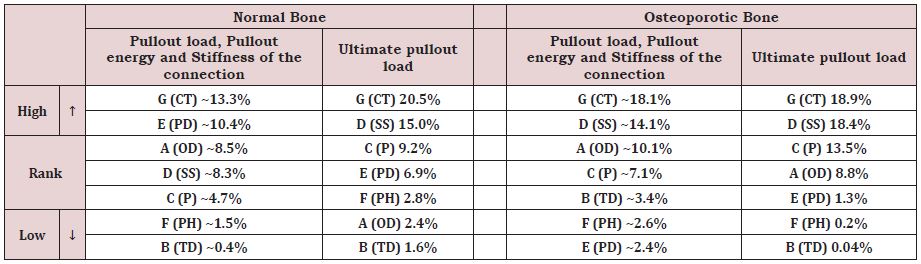
Classification of Design Parameters for Normal and Osteoporotic Bone
Table 9 provides a classification of the design parameters based on the deviation they inflict to the model responses, at both early and final stages of the loading, for normal and osteoporotic bone conditions. The pullout force, energy, and stiffness, computed, at the early stage of loading (10μm prescribed displacement), had basically the same variation and were thereby, grouped in the same cell showing their mean variation. The contact type (CT) parameter, labeled ‘G’, is found to highly influence the model responses at small and large deformations for both normal and osteoporotic bone (up to 20.5% increase). The assumed bonded condition that mimics reproduced a fully Osseo integrated and cemented pedicle screw, substantially improved all model responses in opposition to a frictional contact assumption, representative of a non-cemented, immediately loaded pedicle screw (Table 9). The use of a conical screw instead of a cylindrical one, explored through the (SS) parameter or ‘D’, had the second highest impact on the ultimate pullout force, irrespective of bone condition. Indeed, Table 9 shows that cylindrical-shaped pedicle screws improve the strength and stiffness, particularly in osteoporotic bone where the ultimate pullout force augmented by 18.4%.
The parameter ‘C’ or pitch (P) is ranked third most influencing factor. Indeed, reducing the screw pitch from 2.5mm to 1.75mm enhanced the ultimate pullout force in normal and osteoporotic bone by 9.2% and 13.5%, respectively and had a lesser impact on the strength and stiffness at 10μm for both bone conditions. A large pedicle diameter (PD) or parameter ‘E’ is not found to enhance the strength and stiffness in osteoporotic bone since the variation trend, shown in Table 9, increased by less than 2.4%. In normal bone, however, this parameter had a more substantial impact particularly under small deformations (~10.4% increase) which enabled it to be second most influencing parameter.
Increasing the screw’s outer diameter (OD) or parameter ‘A’ from 6mm to 6.5mm affects favorably the strength and stiffness of the bone-screw compound in the early stages of the loading with 8.5% and 10.1% improvements for normal and osteoporotic bone, respectively. In the later stages of loading, the osteoporotic bone still experiences amelioration in the ultimate pullout force (8.8%) opposed to normal bone whose ultimate pullout is faintly affected (2.4%). The weakest influence on normal and osteoporotic bone types is realized by parameters ‘B’ thread depth (TD) and ‘F’ preparation hole (PH), with the variations reaching less than 3.4% for the former parameter in osteoporotic bone condition and 2.8% the latter in case of normal bone (Table 9).
Immediate Versus Delayed Rupture in Bone after Pullout
Load-displacement curves for Test 3 and Test 8, performed for normal bone under large deformations, are plotted alongside in Figure 4. Test 3 and Test 8 have in common three parameters; a bonded contact, a 1mm thread depth and pedicle diameter of 11mm. Test 8 is furthermore distinguished by its fitting, conical shaped screw, larger nominal outer diameter of 6.5mm and smaller pitch of 2.5mm. In such tests, the ABAQUS explicit dynamic solver is used, simulating a 500μm prescribed displacement of at a rate of 2mm/min, while computing the resistive force or ‘pullout’.
The fast and slow occurrence of the rupture is dictated by the screw design, which determines the amount of bone enclosed between the threads and also by the nature of bone itself, being hard and brittle when it comes to cortical type, ductile and highly ductile in the case of subcortical and trabecular bone type, respectively. The phase O-A, common to both tests, is an adaptation phase in which only moderate force builds up as the bone-screw contact is progressively established. Almost linear phases A-B1 and A-B2 phases characterize the stiffness of screw-bone complex until the ultimate loads are reached. The plateaus B1-C1 and B2-C2, represent a state of quasi equilibrium portrayed by an overall load stabilization, where minor fluctuations indicate the advent of early sequential failure of the bone tissue engaged between the threads. Finally, the last intervals C1-D1 and C2-D2 illustrate the abrupt and unpredictable failure of the bone-screw assemblage.
Test 8 displayed a lower ultimate pullout force, shorter plateau and faster rupture compared to Test 3. The pullout phase in Test 3 started at a screw displacement of ~0.2mm, embodied by the rupture of the pedicle’s cortex considered as the first barrier. This trend is followed by a plateau up to 0.325mm displacement beyond which the abrupt failure takes place leading to a complete rupture attained around 0.415mm screw displacement (Figure 4).
Visualization of the Bone Sites at High Risk of Failure
Pullout is a phenomenon that usually occurs in an abrupt and unpredictable manner. From a mechanical point of view, the failure is unstable happening in very short time, unlike fatigue fracture which develops and propagates gradually during prolonged periods. Resolutions of problems in fracture mechanics for a given structure are generally based on laws of a phenomenological nature where one takes into account the loading, the interactions and the environment (dry, wet … etc.). It is therefore a multifactorial problem that addresses the mechanisms of rupture of a biological structure in perpetual change (bone remodeling) and so are its mechanical properties. In this numerical study, the parameters that influence the pullout of the pedicle screw are multiple as they are dissimilar, in normal and osteoporotic bone. Therefore, the analysis of the model response step-by-step is important to capture the highly deformed zones prone develop the initial crack.
Observation of the output results computed for the eight Taguchi tests shows the existence of three modes of failure schematized in the Figure 5. In our study, the state of failure is described, in a qualitative manner, as the loss of rigidity for the mesh elements reaching critical stress and strain values. For a more accurate representation of the bone’s behavior in response to pullout, it is preferable to integrate adaptive mesh controls implementing criteria that account for the instantaneous bone rupture as well as the remodeling process.
The visualization of the von-Mises stress distribution in the model constituents shows, for the majority of the tests, that the stresses are concentrated in three zones: Zone A, shown in Figure 5a, lays between the pedicle connector and the body of the vertebra inducing a very active shear state. In this configuration the detachment of the entire pedicle capsule is expected. Zone B outlines the upper inner region of the pedicle being stressed due to the resulting axial load as well as the subsequent moment that tend to rip the pedicle cortex from the underlying subcortical bone causing a state of maximum deformation at fracture (Figure 5b). Zone C delineates the contact between the first thread and the cortical wall. Figure 5c illustrates stress concentration that tends to shear the cortical layer in the direction of the pull.
It is well established that the nature of the grouped parameters tackling; the geometry of the screw, morphology of the vertebra and surgical procedure specific to the screw insertion technique, can dictate the vertebral mode of rupture in large deformations. A 3D representation is generated from the 2D axisymmetric model by revolving the screw and the ripped bone matter around the axis of symmetry for better visualization (Figure 6). In the case of Test 3, the damage caused by the pullout to the bone is devastating in such a way that both pedicle and screw get detached (Figure 6a), making the fracture repair surgery very delicate. Moreover, in the case of Test 2, the damage (Figure 6b), is less destructive with a reduced amount of bone torn including the pedicle cortex, less debris occasioned and therefore easier fracture repair and shorter debridement procedures are required. The least overwhelming damage occurs for Test 8 in which the screw is pulled out along with the layers of cortical, subcortical, and trabecular bone confined between the threads (Figure 6c).
Bone fragments following fracture have random shapes and dimensions. Figure 7 shows some of the most common failure modes observed in clinical practice [24]; [25]. The amount of energy stored and released at fracture helps classify the failure modes according to the degree of severity. The most severe failure mode, type A, is manifested in the work of Rohmiller [24] who pulled his screw coated with an acrylic cement layer to ensure a good cohesion with the vertebrae (Figure 7a), this mode is likewise observed in the current study, for instance, in Test 3 that provided the best resistance to pullout and thus, the highest strain energy stored in bone before the disruption is intensely released provoking the abrupt splitting of the pedicle. The type B, shown in Figure 7b is characterized by the pedicle cortex breakage accompanied by the shearing of the subcortical and trabecular bone strips confined between the screw threads as observed in Test 2. The least severe, type C failure mode, depicted in Figure 7c, shows that the screw literally slips outside the vertebra without impairing the pedicle that remained undamaged. In our study this failure more happened when the thread depth is the lowest, the preparation hole providing a clearance between bone and screw is adopted or when the ratio of the pedicle diameter to the screw diameter is the high as in Test 8 for instance.
Statistically, throughout the eight (8) Taguchi’s tests, performed on both normal and osteoporotic bone, the ‘Type A’ rupture occurred 2 times in normal bone only. The ‘Type B’ mode happened equally 3 times in normal and osteoporotic bone, respectively. Finally, the ‘Type C’ rupture mode occurred 3 times in normal bone and 5 times in osteoporotic.
CONCLUSION
The 2D axisymmetric models of the vertebra-pedicle screw is adopted to minimize the simulations’ computation costs. Clinical parameters such as the screw insertion type and depth, the bone density, and the patient degree of mobility, greatly affect the mechanisms of the implant’s failure/success. The design of Taguchi arrays is made on the choice of pertinent parameters known to most influence the biomechanical response of the pedicle screwvertebral bone complex. The Taguchi method helped, thus, in the selection of only eight (8) simulation tests instead of (27) where the number seven (7) stands for the number of chosen parameters and two (2) represents the number of levels.
All computations intended to reproduce some of the physiological loading encountered in the normal spine during day-to-day activities. The elastoplastic stress-strain relationships characteristic of the normal and osteoporotic vertebral bone along with the ‘delete element’ option in the axisymmetric mesh generation process helped in the prediction of the failure mechanisms of pedicle screw-bone complex.
The design parameters were classified according to the deviation they impose to the strength and stiffness of each model configuration, assuming a normal and osteoporotic bone conditions, respectively. Bonded contact between the fully Osseo integrated bone and a cylindrical-shaped screw produced the highest impact on the model responses inducing the best pullout strength, the largest strain energy stored and the most severe damage at failure. Smooth conical screws with small thread depth and pitch led to the least resistance to pullout. The vertebral failure modes depicted in the current study were in good agreement with the clinical findings. These modes were classified into three categories according to degree of severity of the damage known to be closely related to the amount of strain energy stored and released at failure. The most drastic mode led to the intense disruption of the pedicle, the second less severe mode broke the pedicle cortex and the third, least drastic mode, glided the screw outside the vertebra with no impairment on the pedicle.
ACKNOWLEDGEMENT
The authors wish to express their deep gratitude to the surgery team at the M.T. Kassab National Orthopedic Institute, Tunis, Tunisia for their valuable advice and assistance during the setting up of the simulation parameters to mimic the clinical procedures discussed in the manuscript.
REFERENCES
- Lavaste F, Asselineau A, Diop A, Grandjean JL, Laurain JM, et al. (1990) Experimental procedure for mechanical evaluation of dorso-lumbar segments and osteoporosis device. Rachis 2: 435-446.
- Roy-Camille R. (2000) History of spine surgery. Spine News.
- A Said (2006) Treatment des fractures du rachis dorso-lombaire par l’instrumentation postérieure de Cottrel-Dubousset, à propos de 33 cas. Institute National d’Orthopédie Kassab de Tunis. The Graduate Faculty of Medecine of Monastir, Tunisia.
- Nikodem A (2012) Correlation between structural and mechanical properties of human trabecular femur bone. Acta of Bioengineering and Biomechanics 14 (2): 36-46.
- Gohari E, Nikkhoo M, Haghranahi M, Parnianpour M (2013) Analysis of different material theories used in a FE model of a Lumbar segment motion. Acta of Bioengineering and Biomechanics15(2): 33-41.
- Inceoglu S, Ehlert M, Akbay A, McLain RF (2006) Axial cyclic behavior of the bone-screw interface. Medical Engineering & Physics 28(9): 888- 893.
- Waqas AL, Farukh F, Kaddour BM, Hassan A (2017) Drilling resistance: A method to investigate bone quality. Acta of Bioengineering and Biomechanics 19(1): 55-62.
- Zhang QH, Tan SH, Chou SM (2006) Effects of bone materials on the screw pull-out strength in human spine. Medical Engineering & Physics 28(8): 795-801.
- Iyer AS, Christiansen BA, Roberts BJ ,Valentine MJ, Manoharan RK, et al. (2010) Biomechanical model for estimating loads on thoracic and lumbar vertebrae. Clinical Biomechanics 25(9): 853-858.
- Hirano T, Hasegawa K, Takahashi HE, Chiyama SU, Hara T, et al. (1997) Structural characteristics of the pedicle and its role in screw stability. Spine 22(21): 2504-2509.
- Chatzistergosa PE, Magnissalisb EA, Kourkouli SK (2010) A parametric study of cylindrical pedicle screw design implications on the pullout performance using an experimentally validated finite-element model. Medical Engineering & Physics 32(2): 145-154.
- Jendoubi K, Khadri MY, Bendjaballah M, Slimane N (2018) Effect of the insertion type and depth on the pedicle screw pullout strength: A finite element study. Applied Bionics and Biomechanics. 2018:1-9 Article ID 14601195.
- Esenkaya I, Denizhan Y, Kaygusuz MA, Yetmez M, Kelestemur MH (2006) Comparison of the pull-out strengths of three different screws in pedicular screw revision: a biomedical study. Acta Orthop Traumatol Turc 40(1): 72-81.
- Benoit D, Tourbier Y, Toubier SG (1994) Plan d’expérience, Construction, analyse et méthode de Taguchi. Livre Edition Lavoisier, France.
- A Hedhli (2009) Étude et modélisation des implants rachidiens utilisés pour les corrections scoliotiques- Application de la méthode des éléments finis. The Graduate University of Tunis El-Manar, ENIT, Master of Biomedical Technology, Tunisia.
- Linde F, Sorensen H C (1993) The effect of different storage methods on the mechanical properties of trabecular bone. Journal of Biomechanics. 26(10): 1249-1252.
- Mc Kinley TO, Mc Lain RF, Yerby SA, Sarigul-Klijn N, Smith TS (1997) The effect of pedicle morphometry on pedicle screw loading. A synthetic model Spine. 22(3): 246-254.
- Liu CL, Chen HH, Cheng CK, Kao HC, Lo WH (1998) Biomechanical evaluation of a new anterior spinal implant. Clinical Biomechanics 13(1 suppl) S540-S545.
- Chatzistergos PE, Magnissalis E A and Kourkoulis SK (2010) A parametric study of cylindrical pedicle screw design implications on the pullout performance using an experimentally validated finite element model. Medical Engineering & Physics 32(2): 145-154.
- British Standards Institution, Implants for osteosynthesis, Part 5: Bone screws and auxiliary equipment, Section 5.3: Specification for the dimensions of screws having hexagonal drive connection, spherical under surfaces and asymmetrical thread. London 1991.
- B Suneel: Experimental and numerical evaluation of the Pullout strength of self-tapping bone screws in normal and osteoporotic bone. The graduate Faculty of the University of Akron, USA.
- Khadri MY (2009) Etude de l’arrachement des vis pédiculaires par application de la méthode des éléments finis. The Graduate University of Tunis El-Manar, ENIT, Master of Biomedical Technology, Tunisia.
- Li-Chun L, Hsiang-HO C, Su-Ping S (2003) A biomechanical study of the cortex-anchorage vertebral screw. Clinical Biomechanics 18(6): S25-S32.
- Rohmiller MT, Dugan SR, Chris G (2002) Evaluation of calcium sulfate paste for augmentation of lumbar pedicle screw pullout strength. The Spine Journal 2(4): 255-260.
- Abshire BB, McLain RF, Valdevit A, Kambic HE (2003) Characteristics of pullout failure in conical and cylindrical pedicle screws after fullinsertion and back-out. The Spine Journal 1(6): 408-414.
Article Type
Research Article
Publication history
Received date: September 23, 2021
Published date: October 05, 2021
Address for correspondence
Khemaїes Jendoubi, Ecole Nationale Supérieure d’Ingénieurs de Tunis. Tunisia
Copyright
©2021 Open Access Journal of Biomedical Science, All rights reserved. No part of this content may be reproduced or transmitted in any form or by any means as per the standard guidelines of fair use. Open Access Journal of Biomedical Science is licensed under a Creative Commons Attribution 4.0 International License
How to cite this article
Jendoubi K, Bendjaballah M , Khadri Y, Slimane N. Numerical Study of the Pedicle Screws’ Pullout: Design of Experiment and Results Processing Using the ‘Taguchi’ Method. 2021- 3(5) OAJBS.ID.000327.
Figure 1: Development a typical 2D axisymmetric model of the screw and surrounding bone. (a): schematic CAD
representation of the vertebral body and pedicle screw,
(b): idealization of the domain of bone tissue affected by the implant, and
(c): axisymmetric model used in the simulations with focus on the thread’s details.
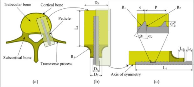
Figure 2: Illustration of the global quadrilateral mesh assigned to the bone (a) and screw (b). Also shown are the magnified zones at the bone-screw interface.
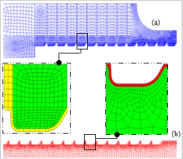
Figure 3: In-vitro experimental pullout test for osteoporotic bone. (a): The experimental device, MTS, Dr. Eden Prairie, MN and (b): The load-displacement curves for ‘conventional and ‘NEW’ pedicle screw designs. Adapted from Lin et al. [23].
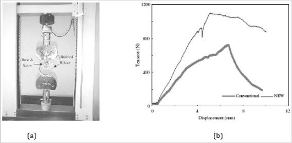
Figure 4: Load-displacement curves for normal bone, plotted for Test 3 and Test 8.
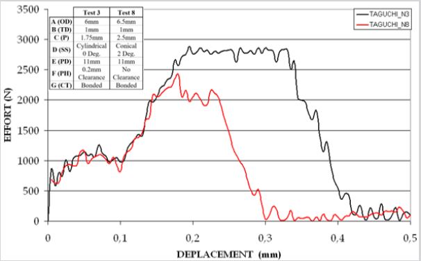
Figure 5: Critical zones in bone depicted according to the computed von-Mises stress for the various tests simulated.
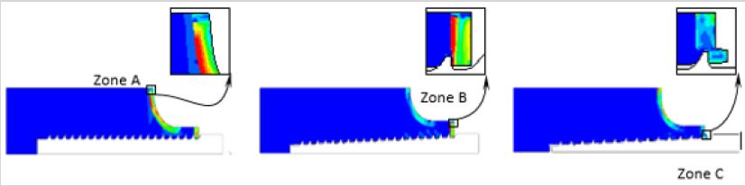
Figure 6: 3D illustration of the axisymmetric model by revolving the pedicle screw and the torn matter, 360º around the axis of revolution for Test 3, Test 2 and Test 8, respectively.
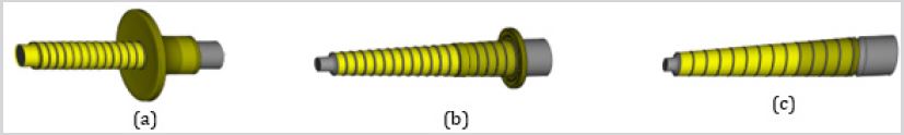
Figure 7: In-vitro experimental tests displaying the vertebral failure modes under pullout forces [24,25].
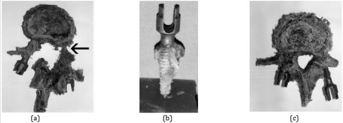
Table 1: Description and values of the parameters used in the model generation.
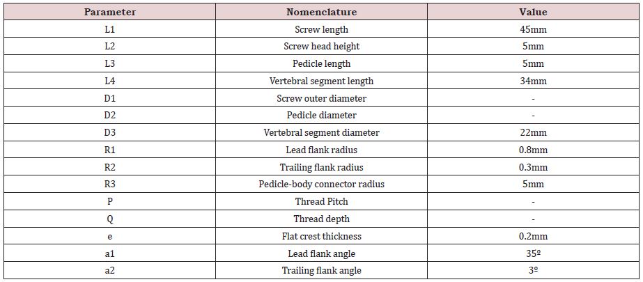
Table 2: Material properties adopted for normal and osteoporotic bone structures as well as the titanium alloy used for the pedicle screws.
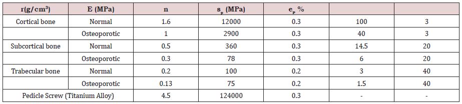
Table 3: Material properties adopted for normal and osteoporotic bone structures as well as the titanium alloy used for the pedicle screws.
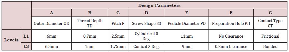
Table 4: Layout of the Taguchi L8 array displayed in the demarcated area, each row indicates the test number, the parameter levels addressed, and the output performance reached. Also shown besides each test is the corresponding CAD model.
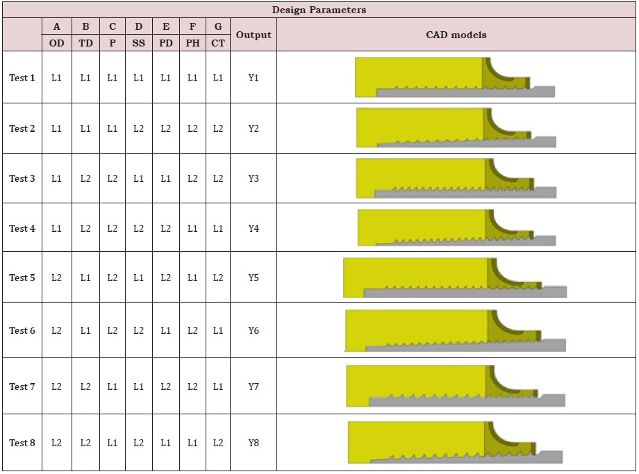
Table 5: ‘Taguchi’ test results for the normal bone.
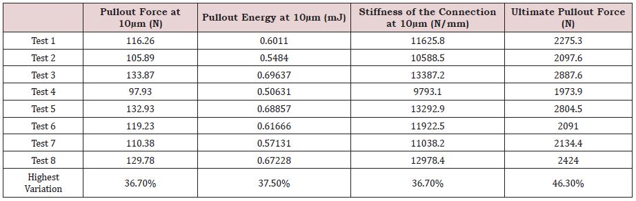
Table 6: Impact of each parameter’s levels on the model responses for normal bone. Trend (arrows) and percentage of variation are also shown.
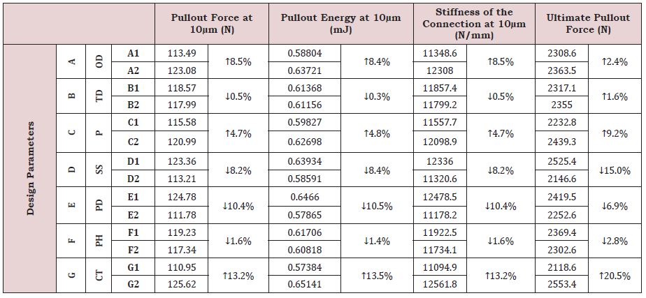
Table 7: ‘Taguchi’ test results for the osteoporotic bone.
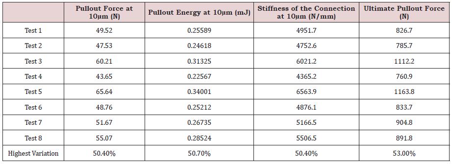
Table 8: Impact of each parameter’s levels on the model responses for osteoporotic bone. Trend (arrows) and percentage of variation are also shown.
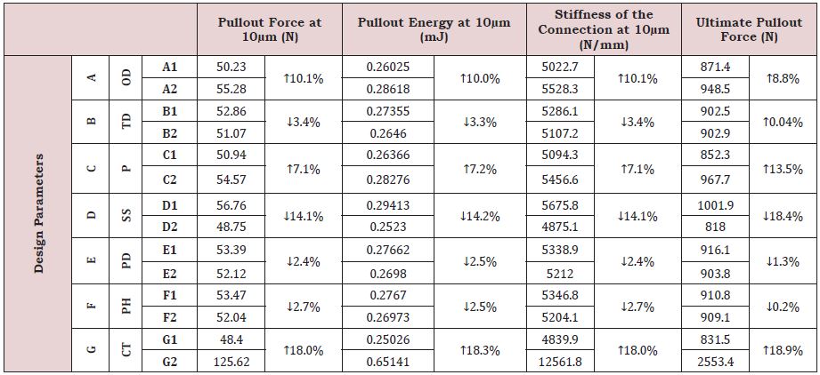
Table 9: Classification of design parameters according to their degree of influence (high to low) on the model responses for normal and osteoporotic bone.